ApparatusBuilding RentalsDowntown ParkingEventsFirearms LicensingINDOT LPA ProjectsLine LocatingNew CustomersOrdinance ViolationOrdinance ViolationParking RegulationsParking SchedulesParking TicketsPlymouth Public PoolRecyclingSection 1 - AdministrationLeague InformationSection 2 - Submission and Approval ProcessSection 3 - Specifications and Technical InformationShelter RentalsSix Minimum Control MeasuresSmall Cell FacilitiesSmoke Detector ProgramSnow PlowingSoliciting
More information coming soon.
Rental Facilities
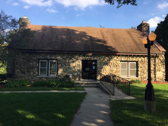
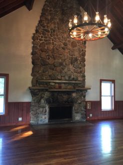
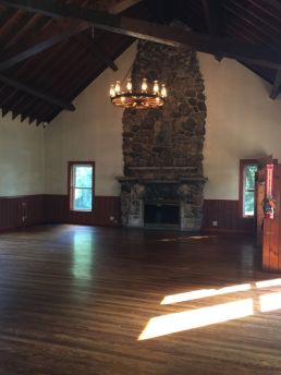
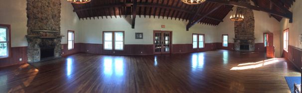
Conservation Club House - 720 Magnetic Parkway, Plymouth, IN 46563
This facility is located on 16 beautiful acres bordering the Yellow River on Plymouth's north side. It has been declared a historic landmark. The WPA built structure offers a large main floor with two stone fireplaces, hardwood floors and wicker furniture, which gives it a real rustic charm. On the lower level you will find a full kitchen that includes a stove, refrigerator and a triple sink. The lower level also has a large dining area that seats approximately 100 people. On the grounds there is a playground, a natural flowing well, a fishing pond and plenty of open area for outdoor activities.
 |
 |
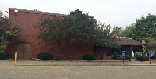
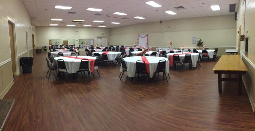
Webster Recreation Center - 110 Webster Avenue, Plymouth, IN 46563
This multi-use building is set on four acres of pleasantly landscaped grounds on the south side of Plymouth. Inside has a fully equipped kitchen and handicapped accessible restrooms. This facility can accommodate approximately 125 people. Surrounding the structure, you will have access to a picnic shelter, new playground equipment, a baseball diamond and two basketball goals.

 |
 |
Click here for a map to locate these facilities:
Rates:
- Resident - $300.00 plus sales tax/day plus $200.00/refundable deposit
- Non-Resident - $400.00 plus sales tax/day plus $200.00/refundable deposit
Rental time is from 8:00 a.m. - 11:00 p.m. NO Additional hours
The facilities may also be rented for an additional $50.00 after 5:00 p.m. the day before your event.
Weekday Special! Rent the Conservation Clubhouse or Webster Recreation Center anytime from 8:00 a.m. - 4:00 p.m. for $50.00 for the first two hours and $25.00 each additional hour. There is no deposit required for weekday rentals. This special does not include holidays.
Payment is expected within fifteen days from original contract or registration will be forfeited. We must be notified 30 days in advance for you to receive a cancellation refund. There will be a $15.00 administrative fee charged for any cancellation.
For reservations call 574-936-2876.
Click here to view our rental policy.
Upcoming Events:
- Daddy Daughter Dance 2025
- Saturday, February 22, 2025
- Riverside Intermediate School
- 6:00 - 8:00pm
- Tickets $20/couple, $2 for each add'l daughter
- Tickets are on sale now @ the park office


Plymouth Greenways Trail Phase II
- Completed, 2019
Hoham Drive
- N. Michigan Street to 400' West of Western Avenue
- Preliminary Engineering
Laporte Street Footbridge
- Preliminary Engineering
CCMG Projects
- 2019 - Ferndale Street & Airport Road
More information coming soon.
2025 Rates

Pool passes, swimming lessons, and pool parties must all be purchased at the Plymouth Park Dept office - NOT at the pool.
Registration for 2025 Group Swimming Lessons:
Click HERE for registration form. Completed forms can be dropped off at the park office, 1660 N Michigan St, Plymouth, IN 46563 or emailed to parkrec@plymouthin.com.
Registration for 2025 Private Swimming Lessons:
Click HERE for registration form. Completed forms can be dropped off at the park office, 1660 N Michigan St, Plymouth, IN 46563 or emailed to parkrec@plymouthin.com.
Empty. Clean. Dry. The New Way to Recycle.
Reduce. Reuse. Recycle. Anyone growing up in the 1970s, '80s or '90s learned the three Rs of recycling in school. We were taught to recycle everything we could. We added recycling containers to our homes, our offices and classrooms and recycling became a part of our culture.
In the 40 years since recycling was introduced, Americans have recycled nearly 87 million tons per year. That means each of us recycles approximately 1.5 pounds per day! However, the recycling model we all grew up with is changing, and we have to change with it.
Trying to recycle unclean or unrecyclable material increases sorting time and slows down the recycling process, damages the facility's equipment and causes contaminants in the bales of clean recyclables that decreases the value of the items. When this occurs, we have to put the ENTIRE load of recyclables into our landfills due to the contamination.
- EMPTY means making sure there is no food or product residue. Make sure all of that goes into the trash or down the drain as part of the EMPTY process.
- CLEAN means that empty recyclable containers should be rinsed. So, no mustard in the mustard containers or leftover ketchup in the ketchup bottles. If you cannot get a container completely clean, it is best to put it into the trash so as not to contaminate the rest of your recycling material and the overall process.
- DRY means letting containers dry before placing them in your blue container so that the paper and cardboard does not get wet. Wet or soiled paper and cardboard cannot be recycled.
By practicing Empty. Clean. Dry. With our families, we can ensure the recycling materials leaving our homes are in fact recyclable. Together, we are caretakers of this blue planet - our home, and largely covered with blue waters that flow beneath blue skies. It is worthy of every effort we can make to protect it for our children's children.
Be sure your recyclables are Empty. Clean. Dry.TM before placing them in your recycling container.
Did You Know?
- Grocery bags ARE NOT recyclable and often contaminate other recyclables.
- Never recycle diapers! Baby diapers are the most common contaminant in the recycling stream.
- Only the clean lid of a pizza box is recyclable; not the greasy bottom.
- Yard waste cannot be placed inside your recycling container.
I. Purpose
Whereas the smaller streams and drainage channels serving the City of Plymouth may not have sufficient capacity to receive and convey storm water runoff, resulting when land use changes from open or agricultural use to a more urbanized use; and whereas the deposit of sediment from developments during and after construction can reduce capacities of storm sewers and drainage systems and result in damages to receiving lakes and streams; therefore, the City of Plymouth adopts this storm water drainage ordinance with the purpose of controlling urban runoff and minimizing urban flooding.
II. Storm Water Control Policy
It shall be the policy of the City of Plymouth that the storage and controlled release of storm water runoff shall be required of all new development, any redevelopment, and other new construction within the City Limits. Retention facilities shall be sized to hold 25 gallons per 100 square feet of hard surface area. In addition, the release rate of storm water from developed lands shall not exceed the release rate from the land area in its present land use.
The owner, developer, or builder must submit detailed computations of runoff before and after development, redevelopment, or new construction which demonstrate that runoff will not be increased. These computations must show that the peak runoff rate after development for the 100 year return period storm of 24 hour duration must not exceed the 10 year return period pre-development peak runoff rate. (The critical duration storm is that storm duration that requires the greatest detention storage.)
Computations for Areas up to and including 200 acres may be based on the Rational Method; typical runoff coefficients are listed herein. For Areas larger than 200 acres, hydrograph techniques and/or computer drainage modeling methods may be used. Hydrograph techniques and computer modeling methods used to determine storm water runoff shall be proven methods, subject to approval of the Sanitary Board of Trustees.
Because topography and the availability and adequacy of outlets for storm runoff vary with almost every site, the requirements for storm drainage tend to be an individual matter for any project. It is recommended that each proposed project be discussed with the City Sewer Superintendent and the City Engineer, at the earliest practical time in the planning stage.
III. When Effective
This ordinance shall become effective after its final passage, approval and publication as required by law.
IV. Conflicting Ordinances
The provisions of this ordinance shall be deemed as additional requirements to minimum standards required by other ordinances of the City or other governing agencies. In the case of conflicting requirements, the most restrictive shall apply.
V. Repealer
All ordinances or parts thereof in conflict with the provisions of this ordinance are repealed.
VI. Compliance with other Ordinance
In addition to the requirements of this ordinance, compliance with the requirements set forth in other applicable ordinances with respect to submission and approval of preliminary and final subdivision plats, improvement plans, building and zoning permits, construction inspections, appeals, and similar matters, and compliance with applicable State of Indiana statutes and regulations shall be required.
VII. Disclaimer or Liability
The degree of protection required by this ordinance is considered reasonable for regulatory purposes and is based on historical records, engineering, and scientific methods of study. Larger storms may occur or storm water runoff depths may be increased by man-made or natural causes. This ordinance does not imply that land uses permitted will be free from storm water damage. This ordinance shall not create liability on the part of the City of Plymouth, the Sanitary Board of Trustees, the City Sewer Superintendent, the City Engineer, or any officer or employee thereof for any damage which may result from reliance on this ordinance or on any administrative decision lawfully made thereunder.
VIII. Corrective Action
Nothing herein contained shall prevent the City of Plymouth, the Sanitary Board of Trustees, the City Sewer Superintendent, or the City Engineer from taking such other lawful action as may be necessary to prevent or remedy any violation. All costs connected therewith shall accrue to the person or persons responsible.
IX. Connection to a County Regulated Drain
I.C. 36-9-27-17 requires that a new drain connecting into a regulated drain under the jurisdiction of the Marshall County Drainage Board must have the approval of the Marshall County Surveyor.
X. Permits for Construction in the Floodway
Chapter 318 of the Acts of 1945, as amended, Sections 17 and 19, require the Natural Resources Commission approval of any construction in a floodway, and of any works for flood control. This includes bridges, dams, levees, dikes, floodwalls, wharves, piers, dolphins, booms, weirs, bulkheads, jetties, groins, excavations, fills or deposits of any kind, utility lines, or any other building, structure, or obstruction. Also, any ditch work (new construction, deepening or modification) within one half mile of a public freshwater lake of 10 acres or more in area.
The approval of the Natural Resources Commission, in writing, must be obtained before beginning construction. Applications approval should be submitted to:
Department of Natural Resources
Division of Water
2475 Directors Row
Indianapolis, IN 46241
All applications should be made on the standard application form provided by the Natural Resources Commission and should be accompanied by plans, profiles, specifications, and other data necessary for the Natural Resources Commission to determine the effect of the proposed construction upon the floodway and on flood control in the state.
Application made to and approval granted by the Natural Resources Commission does not in any way relieve the owner of the necessity of securing easements or other property rights, and permits and/or approvals from affected property owners and local, state, and federal agencies.
The engineering staff of the Division of Water is available to discuss and offer suggestions regarding requirements in the design of structures in floodways. High water marks have been set on many of the streams in the state, and information is available from the Division of Water on actual and/or potential flooding. Information regarding bench marks set to Mean Sea Level Datum, General Adjustment of 1929, is available from the Division of Water, Surveying and Mapping Section.
Applications are considered by the Natural Resources Commission at regular meetings usually held each month. After the application and plans have been approved by the Natural Resources Commission, a certificate of approval is forwarded to the applicant.
A fee is charged by the Natural Resources Commission for approvals under the Flood Control Act. Unless stated otherwise in the approval, construction is considered to be a permanent development, and no renewals of the approvals are granted for temporary construction. The right is reserved to require additional data where necessary.
XI. Definitions
For the purpose of this ordinance, the following definitions shall apply:
A. Capacity of a Storm Drainage Facility - The maximum flow that can be conveyed or stored by a storm drainage facility without causing damage to public or private property.
B. Channel - A natural or artificial watercourse which periodically or continuously contains moving water, or which forms a connecting link between two bodies of water. It has a defined bed and banks which serve to confine the water.
C. City Plan Director - The person or entity serving in the capacity of Plan Director or Plan Consultant for the City of Plymouth.
D. Compensatory Storage - An artificial volume of storage within a floodplain used to balance the loss of natural flood storage capacity when artificial fill or structures are placed within the floodplain.
E. Contiguous - Adjoining or in actual contact with.
F. Culvert - A closed conduit used for the passage of surface drainage water under a roadway, railroad, canal, or other impediment.
G. Detention - The amount of excess storm water accumulated on the site that may be released at a restricted runoff release rate.
H. Detention Basin - A facility constructed or modified to restrict the flow of storm water to a prescribed maximum rate, and to detain concurrently the excess waters that accumulate behind the outlet.
I. Detention Storage - The temporary detaining or storage of storm water in storage basins, on rooftops, in streets, parking lots, school yards, parks, open spaces, or other Areas under predetermined and controlled conditions, with the rate of drainage therefrom regulated by appropriately installed devices.
J. Drainage Area - The area from which water is carried off by a drainage system; a watershed or catchment area.
K. Drop Manhole - A manhole having a vertical drop pipe connecting the inlet pipe to the outlet pipe. The vertical drop pipe shall be located immediately outside the manhole.
L. Dry Bottom Detention Basin - A basin designed to be completely dewatered after having provided its planned detention of runoff during a storm event.
M. Duration - The time period of a rainfall event.
N. Erosion - Wearing away of the land by running water, waves, temperature changes, ice or wind.
O. Flood Elevation - The elevation at all locations delineating the maximum level of high waters for a flood of given return period and rainfall duration.
P. Flood or Flood Waters - The water of any watercourse which is above the banks of the watercourse. It also means the water of any lake which is above and outside the banks thereof.
Q. Flood Hazard Area - Any flood plain floodway, floodway fringe, or any combination thereof which is subject to inundation by the regulatory flood; or any flood plain as delineated by Zone A of a Flood Hazard Boundary Map.
R. Flood Plain - The area adjoining the river or stream which has been or may hereafter be covered by flood waters.
S. Flood Protection Grade - The elevation of the lowest floor of a building. If a basement is included, the basement floor is considered the lowest floor.
T. Floodway - See Regulatory Floodway
U. Floodway Fringe - That portion of the flood plain lying outside the floodway, which is inundated by the regulatory flood.
V. Footing Drain - A drain pipe installed around the exterior of a basement wall foundation to relieve water pressure caused by high groundwater elevation.
W. Grade - The inclination or slope of a channel, canal, conduit, etc., or natural ground surface usually expressed in terms of the percentage the vertical rise (or fall) bears to the corresponding horizontal distance.
X. Impact Areas - Areas defined and mapped by the City of Plymouth are unlikely to be easily drained because of one or more factors including but not limited to any of the following: soil type, topography, land where there is not adequate outlet, a floodway or floodplain, land within 75 feet of each bank of any regulated drain or within 75 feet from the centerline of any regulated tile ditch.
Y. Impervious - A term applied to material through which water cannot pass, or through which water passes with difficulty.
Z. Inlet - An opening into a storm sewer system for the entrance of surface storm water runoff, more completely described as a storm sewer inlet.
AA. Junction Chamber - A converging section of conduit, usually large enough for a person to enter, used to facilitate the flow from one or more conduits into a main conduit.
BB. Lateral Storm Sewer - A sewer that has inlets connected to it but has no other storm sewer connected.
CC. Manhole - Storm sewer structure through which a person may enter to gain access to an underground storm sewer or enclosed structure.
DD. Major Drainage Systems - Drainage systems carrying runoff from an area of one or more square miles.
EE. Minor Drainage Systems - Drainage systems having an area of less than one square mile.
FF. Off-Site - Everything not on site.
GG. On-Site - Located within the controlled area where runoff
originates.
HH. Outfall - The point or location where storm runoff discharges from a sewer or drain. Also applies to the outfall sewer or channel which carries the storm runoff to the point of outfall.
II. Peak Flow - The maximum rate of flow of water at a given point in a channel or conduit resulting from a particular storm or flood.
JJ. Plan Commission - The City of Plymouth Planning Commission.
KK. Radius of Curvature - Length of radius of a circle used to define a curve.
LL. Rainfall Intensity - The cumulative depth of rainfall occurring over a given duration, normally expressed in inches per hour.
MM. Reach - Any length of river, channel or storm sewer.
NN. Regulated Area - All of the incorporated land within the City of Plymouth and the area located within the two-mile zoning boundary of the City of Plymouth.
OO. Regulatory Flood - That flood having a peak discharge which can be equaled or exceeded on the average of once in a one hundred (100) year period, as calculated by a method and procedure which is acceptable to City of Plymouth. If a permit from the Natural Resources Commission for construction in the floodway is required (see Section 1, X., page 3), then the regulatory flood peak discharge should be calculated by a method acceptable to the City and the Natural Resources Commission. This regulatory flood is equivalent to a flood having a probability of occurrence of one percent (1%) in any given year.
PP. Regulatory Floodway - The channel of a river or stream and those portions of the floodplains adjoining the channel which are reasonably required to carry and discharge the peak flow of the regulatory flood of any river or stream.
QQ. Release Rate - The amount of storm water release from a storm water control facility per unit of time.
RR. Retention - The amount of storm water to be kept on the site. This storm water is utilized to recharge the ground water table through drywells, percolation, etc.
SS. Retention Basin - A facility constructed or modified to be used as a ground water recharge area. This basin does not release water off the site.
TT. Return Period - The average interval of time within which a given rainfall event will be equalled or exceeded once. A flood
having a return period of 100 years has a one percent probability of being equalled or exceeded in any one year.
UU. Runoff Coefficient - A decimal fraction relating the amount of rain which appears as runoff and reaches the storm drainage system to the total amount of rain falling. A coefficient of 0.5 implies that 50 percent of the rain falling on a given surface appears as storm water runoff.
VV. Sanitary Board of Trustees - That governing body, or their appointed representative, designated by the City of Plymouth to regulate the storm water system within the corporate limits (including all inlets, manholes, piping, and basins that convey or contain storm water), and to review and approve drainage plans within the two-mile zoning boundary.
WW. Sediment - Material of soil and rock origin, transported, carried or deposited by water.
XX. Siphon - A closed conduit or portion of which lies above the hydraulic grade line, resulting in a pressure less than atmospheric and requiring a vacuum within the conduit to start flow. A siphon utilizes atmospheric pressure to effect or increase the flow of water through a conduit. An inverted siphon is used to carry storm water flow under an obstruction such as a sanitary sewer.
YY. Spillway - A waterway in or about a hydraulic structure, for the escape of excess water.
ZZ. Stilling Basin - A basin used to slow water down or dissipate its energy.
AAA. Storage Basin - A generic term used to identify Detention Basin and/or Retention Basin.
BBB. Storage Duration - The length of time that water may be stored in any storm water control facility, computed from the time water first begins to be stored.
CCC. Storm Sewer - A closed conduit for conveying collected storm water.
DDD. Storm Water Drainage System - All means, natural or man-made, used for conducting storm water to, through or from a drainage area to any of the following: conduits and appurtenant features, canals, channels, ditches, streams, culverts, streets and pumping stations.
EEE. Storm Water Runoff - The water derived from rains falling within a tributary basin, flowing over the surface of the ground or collected in channels or conduits.
FFF. Tributary - Contributing storm water from upstream land areas.
GGG. Urbanization - The development, change or improvement of any parcel of land consisting of one or more lots for residential, commercial, industrial, institutional, recreational or public utility purposes.
HHH. Watercourse - Any river, stream, creek, brook, branch, natural or man-made drainageway in or into which storm water runoff or floodwaters flow either regularly or intermittently.
III. Watershed - See Drainage Area.
JJJ. Wet Bottom Detention Basin - A basin designed to retain a permanent pool of water after having provided its planned detention of runoff during a storm event.
Rockie Youth Football
- Garrett Wright 574-780-0789
Volleyball
- Steve Harrell 574-292-2869
Tennis
- Michael Delp 574-935-5201
- Cliff Gunter 574-249-9356
Men's Slowpitch Softball
- Ed Soike 574-780-6865
- Burke Richeson 574-780-0393
- Tricia Hall 574-540-1314
I. Project Sizes and Types that are Regulated by this Ordinance
Any residential, commercial, industrial, or institutional construction project or development that lies within the Regulated Area and has a combined impervious and/or semi-impervious surface area of 4,000 square feet or greater shall be regulated by this ordinance. This includes site improvements as well as buildings. Sites shall be subject to this ordinance when the accumulated sum of the improvements, initiated after the effective date of this ordinance, has a combined impervious and/or semi-impervious surface area of 4,000 square feet or greater.
Furthermore, this ordinance also regulates all major or minor subdivisions, as regulated by the Subdivision Control Ordinance 1481, Plymouth, Indiana, effective Dec. 11, 1989, as amended; and planned unit developments as regulated by the Zoning Ordinance of the City of Plymouth, Ordinance Number 1396, as amended.
For proposed improvements to an existing developed site, the City Sewer Superintendent and the Sanitary Board of Trustees can require additional remedial action to be performed at the site.
The City Sewer Superintendent together with the Sanitary Board of Trustees, after thorough investigation and evaluation, has the authority to waive the requirement of this ordinance.
II. Exempt Projects
The intent of this ordinance is to control runoff and minimize urban flooding. Property owners shall be responsible to minimize runoff of storm water onto neighboring properties. Improvements exempt from this ordinance because of size restrictions, are still required to satisfy the intent of this ordinance. If urban flooding occurs because of an improvement, the owners will be required to take remedial action.
Projects with less than 4,000 square feet of impervious or semi-impervious surfaces are exempt from this ordinance. However, a site shall be subject to this ordinance when the combined sum of the impervious and/or semi-impervious surface area of the improvements initiated after the effective date of this ordinance is 4,000 square feet or greater. This ordinance shall apply to all projects and improvements which have been initiated since the effective date of this ordinance.
III. Legal Drains
Permission must be obtained from the Marshall County Surveyor to outlet any piped or runoff drainage into a legal drain. Furthermore, if the drainage is piped to the legal drain, any pipe outlet 12" or larger in diameter must also be approved by the Marshall County Drainage Board.
IV. Application and Review Procedure
The Sanitary Board of Trustees may appoint a representative to act on its behalf, including but not limited to: the City Sewer Superintendent, the City Engineer, or a firm appointed for the purpose of carrying out this ordinance. Said representative may be given the authority to approve drainage plans, without the assemblage of the entire board. Said representative will have thirty (30) days to act on a project, once a complete submission has been made.
A. An Application for Drainage Plan Approval shall be obtained from and filed with the Plymouth City office at 124 North Michigan Street. The completed Application must be filed at least twenty-one (21) days prior to the regularly scheduled meeting of the Sanitary Board of Trustees. The Application must be accompanied by five (5) copies of the Preliminary and/or Final Drainage Plan, and all required information and data.
B. Upon receipt of the Application for Drainage Plan Approval, the City Sewer Superintendent will review the proposed drainage plans to determine whether they have been prepared in accordance with the terms of this Ordinance.
(1) If the City Sewer Superintendent finds that the Application and plans have been submitted with the correct informational requirements and has been prepared in accordance with the terms of this ordinance, then he shall forward a report so stating to the Sanitary Board of Trustees for their consideration.
(2) If the City Sewer Superintendent finds that the Application and plans have not been submitted with the correct informational requirements or has not been prepared in accordance with the terms of this Ordinance, he shall advise the applicant in writing of the items of non-conformance.
a. If the applicant submits additional and/or revised information and plans as requested, at least one week prior to the regularly scheduled meeting, the City Sewer Superintendent shall re-review said drainage plans to determine their conformance prior to the regularly scheduled meeting.
b. If the applicant fails to submit additional and/or revised information and plans in a timely manner, the Sanitary Board of Trustees shall not review the drainage plans until such time that all additional and/or revised information has been submitted and reviewed by the City Sewer Superintendent.
(3) The City Sewer Superintendent may contact the City Engineer for technical assistance at any time during this process.
(4) Financial guarantees are a prerequisite to approval of a Final Drainage Plan. See Section 2-V.
C. Upon receipt of the report from the City Sewer Superintendent, the Sanitary Board of Trustees shall, at their regularly scheduled meeting, review the Preliminary and/or Final Drainage Plan along with the accompanying data and determine whether or not the Drainage Plan meets all of the minimum requirements and standards of this Ordinance. The Sanitary Board of Trustees shall then take one of the following actions on the application within thirty (30) days after all completed information and plans have been submitted, or an extension is mutually agreed upon.
(1) Conditional Approval. If the Sanitary Board of Trustees determines that upon the satisfactory completion of one or more specified conditions consistent with the requirements, standards and specifications of this Ordinance, the Sanitary Board of Trustees may give conditional approval to the Drainage Plan.
(2) Approval. The Sanitary Board of Trustees shall give Drainage Plan Approval only after it has determined that the Drainage Plan meets the requirements of this Ordinance. Approval of a Final Drainage Plan requires that sufficient financial guarantees have been submitted in accordance with this Ordinance.
(3) Disapproval. Should the Sanitary Board of Trustees disapprove the Drainage Plan, written notice of such action, together with reasons therefor, shall be transmitted to the applicant. Such action shall also be entered on the official records of the Board. If disapproved, the applicant may at any time reapply for Drainage Plan Approval.
(4) Refer to City Sewer Superintendent. Should the Board of Sanitary Trustees have a question about a specific technical aspect of the Drainage Plan, the Sanitary Board of Trustees may refer a question to the Sewer Superintendent for a finding. The Sewer Superintendent may request the assistance of the City Engineer if he so desires.
D. Upon approval of the Preliminary/Final Drainage Plan, the City Sewer Superintendent shall affix his signature to the Application for Drainage Plan Approval. Action taken by the Sanitary Board of Trustees shall be entered in the minutes of the meeting along with the written reasons for said action.
(1) No Building Permits or Improvement Location Permits will be issued by the City Building Commissioner or other co-adopting localities for any construction, improvements, or developments that are regulated by this ordinance unless they receive a copy of the Application for Drainage Plan Approval signed by the City Sewer Superintendent, or a waiver signed by the City Sewer Superintendent.
(2) Copies of the Application for Drainage Plan Approval, signed by the City Sewer Superintendent, shall be submitted to the Plymouth Plan Commission along with submission of the final plat. The Plymouth Plan Commission shall not approve a final plat without reviewing the signed Application.
(3) Real estate may not be sold until such time that the Application for Drainage Plan Approval has been signed by the City Sewer Superintendent, financial guarantees have been satisfied, and the Final Plat has been approved by the Plymouth Plan Commission and has been recorded.
(4) Final approval of the Drainage Plan by the Sanitary Board of Trustees shall not be construed as an acceptance of any street dedication or approval of any building permit which requires the approval of other state or local agencies which have jurisdiction.
E. Approval of the Preliminary Drainage Plan only authorizes the developer/builder to begin grading and installation of drainage improvements, after securing other necessary approvals and permits.
V. Financial Guarantees
Financial guarantees, provided by the property owner, shall be a prerequisite to the Sanitary Board of Trustees' action on the application for the approval of the Final Drainage Plan. The Sanitary Board of Trustees shall approve the Final Drainage Plan only after one of the following actions has been taken:
A. A certification has been submitted to the effect that the drainage improvements have been graded and installed in accordance with the specifications of this Ordinance, following Preliminary Drainage Plan approval.
B. A performance bond is posted with the Board of Public Works and Safety. Said bond shall:
(1) Run to the City of Plymouth Board of Public Works and Safety.
(2) Be in the amount equal to 100 percent of the cost, as estimated by the Board of Public Works and Safety, of all improvements and installations as required under this Ordinance, excluding, however, the cost of any said improvements and installations which have been constructed, installed and completed in compliance with the requirements of this Ordinance prior to the providing of this bond and for which sufficient written proof of such construction, installations and completion has been furnished to the Board of Public Works and Safety and the Sanitary Board of Trustees.
(3) Be satisfactory to the Board of Public Works and Safety.
(4) Run until and terminate sixty (60) days after the filing of a Completion Affidavit with the Plymouth City Office and obtained from the Plymouth City Office.
(5) This bond may be in conjunction with the finanacial guarantees required by the Plymouth Plan Commission for water, sanitary sewer, and road improvements.
C. Cash bonds, certified checks, or certificates of deposit with joint ownership between the Board of Public Works & Safety and the property owner, or other negotiable securities acceptable and assigned to the Board of Public Works & Safety are posted in lieu of the performance bond.
Any funds received from the financial guarantees required by this Ordinance shall be used only for the purpose of making drainage improvements for which said guarantees were provided, in accordance with the specifications and requirements of this Ordinance.
If maintenance is required in the future to bring the drainage features back to design standards, the property owner(s) shall be responsible for providing said maintenance. Should the property owner(s) fail to provide necessary maintenance, the City may provide said maintenance and the property owner(s) will be assessed for the amount of the work.
VI. Certifications Required
After completion of the project and before final acceptance can be made, a professionally prepared and certified "As Built" set of plans and a Completion Affidavit shall be submitted to the City Sewer Superintendent (through the Plymouth City Office) for review.
The plans shall include all pertinent data relevant to the completed storm drainage system and shall include:
A. Pipe size and pipe material.
B. Invert elevations.
C. Top rim elevations.
D. Lengths of all pipe structures.
E. Data and calculations showing detention basin storage volume.
F. Certified statement on plans stating the completed storm drainage system substantially complies with construction plans as approved by the Sanitary Board of Trustees.
All such submitted plans of completed projects shall be reviewed for compliance within 30 days after submission to the City Sewer Superintendent. If notice of non-compliance is not given within 30 days of submission of the plans, the plans shall be construed as approved and accepted.
VII. Changes in Plan
If the applicant wishes to amend the site plan in any way after the Drainage Plan has been approved by the Sanitary Board of Trustees, the applicant must inform the City Sewer Superintendent of the mandated or proposed change. If the City Sewer Superintendent determines the change in the building or site plan significantly changes the drainage as proposed under the currently approved Final Drainage Plan, he may require additional information and that the change be reviewed by the Sanitary Board of Trustees subject to their approval.
VIII. Time to Commence Work
Work shall be commenced within 24 months of approval of the Final Drainage plan or approval shall be withdrawn and the financial guarantees forfeited.
I. Information Requirements
The following information and data provided by an Indiana licensed professional engineer, architect, or land surveyor engaged in storm drainage design shall be required.
A. Topographic and Soils Maps
A soils map of the proposed development indicating soils names and their hydrologic classification must be provided when Soil Conservation Service (SCS) hydrologic methods are used. In addition, a topographic map of the land to be subdivided and such adjoining land whose topography may affect the layout or drainage of the development must be provided.
The contour intervals shall be one foot when slopes are less than four percent and shall be two feet when the slope exceeds four percent. On this map, the following shall be shown:
- The location of streams and other flood water runoff channels, the extent of the floodplains at the established 100 year flood elevation where available (regulatory floodway), and the limits of the floodway, all properly identified.
- The normal shoreline of lakes, ponds, swamps and detention basins, their floodplains, and lines of inflow and outflow if any.
- The location of regulated drains, farm drains, inlets and out-falls, if any of record.
- Storm, sanitary, and combined sewers, and outfalls, if any of record.
- Septic tank systems and outlets, if any of record.
- Seeps, springs, flowing and other wells, that are visible or of record.
B. Preliminary Drainage Plan
A comprehensive plan, in preliminary form (or in combined preliminary and final form), designed to handle safely the storm water runoff and to retain/detain the increased storm water runoff, must be provided.
The plan shall provide or be accompanied by mapsor other descriptive materials indicating the feasibility of the drainage plan and showing the following:
- The extent and area of each watershed affecting the design of retention/detention facilities as shown on USGS Quadrangle Maps or other more detailed maps as required by the Sanitary Board of Trustees.
- The preliminary layout and design of proposed storm sewers, the outfall and outlet locations and approximate elevations, the receiving stream or channel and its 100 year return period water elevation.
- The location and design of the proposed street system, especially including depressed pavements used to convey or temporarily store overflow from the heavier rainstorms, and the outlets for such overflow.
- The locations, cross sections, and profiles of existing streams and floodplains to be maintained, and new channels to be constructed.
- The materials, elevations, waterway openings, and the basis for design of proposed culverts and bridges.
- Existing ponds and basins to be maintained, enlarged, or otherwise altered and new ponds or basins to be built and the basis of their design.
- The estimated depth and amount of storage required in the new ponds or basins.
- The estimated location and percentage of impervious surfaces existing and expected to be constructed when the development is completed.
- Any interim plan which is to be incorporated into the development pending completion of the development and the final drainage plan.
C. Valley Cross Section
One or more typical cross sections must be provided showing all existing and proposed channels or other open drainage facilities carried to a point above the 100 year high water elevation; showing the elevation of the existing land and the proposed changes thereto, together with the high water elevations expected from the 100 year storm under the controlled conditions called for by this ordinance; and showing the relationship of structures, streets, and other facilities.
D. Site Plan
A plan drawn to scale showing dimensions of the site with existing and proposed storm drainage facilities must be provided.
E. Final Drainage Plans
The final plans shall provide or be accompanied by calculations, maps and/or other descriptive material showing the following:
- The extent and area of each watershed tributary to the drainage channels in the development.
- The street storm sewers and other storm drains to be built, the basis of their design, outfall and outlet locations and elevations, the receiving stream or channel and its high water elevation, and the functioning of the drains during high water conditions.
- The parts of the proposed street system where pavements are planned to be depressed sufficiently to convey or temporarily store overflow from storm sewers and over the curb runoff resulting from the heavier rainstorms and the outlets for such overflow.
- Existing streams and floodplains to be maintained, and new channels to be constructed, their locations, cross sections and profiles.
- Proposed culverts and bridges to be built, their materials, elevations, waterway openings and basis of their design.
- Existing storage basins and ponds to be maintained, enlarged, or otherwise altered and new basins or ponds to be built and the basis of their design.
- The estimated location and percentage of impervious surfaces existing and expected to be constructed when the development is completed.
- The slope, type and size of all sewers and other waterways.
- For all storage basins, a plot or tabulation of storage volumes with corresponding water surface elevations and a plot or tabulation of the basin outflow rates for those water surface elevations.
F. Report
A report shall be submitted with the preliminary or final drainage plan that includes the following information:
- A description of the proposed development;
- The current land use conditions;
- The method of hydraulic and hydrologic analysis used, including any assumptions or special condition;
- The results of the analysis; and
- The recommended drainage control facilities.
- Hydraulic and hydrologic calculations, including input and output files, shall be included as appendices to the report.
G. Permission to Connect to Legal Drain
If plans include connection to a legal drain, written permission from the County Surveyor and/or the Marshall County Drainage Board shall be submitted with the preliminary or final drainage plan.
II. System Design Criteria
Plans shall show that provisions have been made for both retention and detention within the limits of the project/ development. The amount of retention shall be 25 gallons per one hundred square foot of hard surface area, as detailed in SECTION 3, III. In addition to this amount to be retained on the property, there shall be detention provided as detailed in SECTION 3, X. The detained amount may be released at the rate specified in SECTION 3, X.
For proposed improvements to an existing developed site, the Sanitary Board of Trustees may require that plans include additional remedial action to be performed at the site.
III. Storm Water Retention
The following shall govern the design of any improvement with respect to the retention of storm water runoff.
A. Acceptable Retention Methods
The portion of the increased storm water runoff resulting from a proposed development should be retained on-site by the provisions of appropriate wet or dry bottom reservoirs, drywells, vegetated shallow depressed areas, or other acceptable techniques. Retention basins shall be sized to hold the excess flows created by the development of the property as based on the amount of hard surface area, drives, parking lots, roofs, etc. This water shall not be released from the property, with the retention basins being utilized as ground water recharge areas.
B. Design Criteria
The design of storm water retention facilities shall be based on the amount of hard surface area. The holding capacity for retention facilities shall be 25 gallon per 100 square feet of hard surface area such as roofs, drives, parking lots, etc.
C. Drainage System Outlet
The site drainage collector system shall be designed to outlet into the site retention facility/facilities. Once the retention facility/facilities has been filled, the remainder of the runoff will then enter into the site detention facility/facilities and from there be released at a 10 year undeveloped release rate.
D. Retention System Overflow Design
The retention facility shall have an overflow which discharges into the detention facility. If the facility is a combination retention/detention facility, the release rate shall be based on the 10 year undeveloped release rate (see SECTION 3, X., C.) after the required retention is held on the site.
E. Hard Surface Definition
Hard Surfaces are surfaces in which the water will run off the drainage area with very little or no ground infiltration. Areas include but are not limited to: building roof areas, asphalt surfaces, concrete surfaces, and compacted limestone surfaces.
F. Determination of Storage Volume
Following is the procedure for retention calculations.
Steps Procedure:
- Determine total hard surface area in square feet = "A".
- Divide the hard surface area by 100 square feet = "A/100".
- Multiply this value (A/100) by 25 gallons.
- This value is the required retention volume in gallons.
- Multiply the required retention (gallons) by .1337 to obtain the required retention volume in cubic feet.
G. General Retention Basin Design Requirements
Basins shall be constructed to retain permanently on site 25 gallons per 100 square feet of hard surface area. The volume of storage provided in these basins, together with such storage as may be authorized in other on-site facilities, shall be sufficient to control the above runoff within the system.
The following design principles shall be observed:
- The maximum volume of water stored and percolated into the soil shall not result in excessive storage durations.
- The maximum planned depth of storm water stored (without a permanent pool) shall not exceed four feet.
- All storm water retention facilities shall be separated by a sufficient amount from any building or structure to be occupied, so that 1) ingress/egress is not impeded and 2) the building or structure is not damaged by the storm water infiltration.
- All excavated excess spoil may be spread so as to provide for aesthetic and recreational features such as sliding hills, sports fields, etc. Slopes no steeper than 6 horizontal to 1 vertical for safety, erosion control, stability, and ease of maintenance shall be permitted.
- Safety screens having a maximum opening of 4 inches shall be provided for any pipe or opening to prevent children or large animals from crawling into the structures.
- Danger signs shall be mounted at appropriate locations to warn of deep water, possible flooding conditions during storm periods and other dangers that exist. Fencing shall be provided if deemed necessary by the Sanitary Board of Trustees.
- Outlet control structures shall be designed to operate as simply as possible and shall require little or no maintenance and/or attention for proper operation. They shall limit discharges into the detention facilities so as not to exceed the predetermined maximum authorized peak flow rate.
- Emergency overflow facilities such as a weir or spillway shall be provided for the release of exceptional storm runoffs or in emergency conditions should the normal discharge devices become totally or partially inoperative. The overflow facility shall be of such design that its operation is automatic and does not require manual attention and its outlet flows into the detention facility.
- Grass or other suitable vegetative cover shall be provided throughout the entire basin area. Grass should be cut regularly at approximately monthly intervals during the growing season or as required.
- Debris and trash removal and other necessary maintenance shall be performed on a regular basis to assure continued operation in conformance to design.
- A report shall be submitted with the preliminary or final plan as stated in Section 3, I., F.
H. Dry Bottom Basin Design Requirements
Retention basins which will not contain a permanent pool of water shall, whenever possible, be designed to serve a secondary or multipurpose function. Recreational facilities, aesthetic qualities (open spaces) or other types of use shall be considered in planning the retention facility.
I. Wet Bottom Basin Design Requirements
Where part of a retention basin will contain a permanent pool of water, all the items required for retention storage shall apply. A controlled positive outlet will be required to maintain the design water level in the wet bottom basin and may provide required detention storage above the design water level.
However, the following conditions shall apply:
- Basins designed with permanent pools or containing permanent ponds shall have a water area of at least one-half acre. If fish are to be maintained in the pond, a minimum depth of approximately 10 feet shall be maintained over at least 25 percent of the pond area. The remaining pond area shall have no extensive shallow areas, except as required by subsection (3) below.
- In excavated ponds, the underwater side slopes in the pond shall be stable. In the case of valley storage, natural slopes may be considered to be stable.
- A safety ledge four to six feet in width is required and must be installed in all ponds approximately 30 to 36 inches below the permanent water level. In addition, a similar maintenance ledge 12 to 18 inches above the permanent water line shall be provided. The slope between the two ledges shall be stable and of a material such as stone or rip rap which will prevent erosion due to wave action.
- A safety ramp exit from the pond is required in all cases and shall have a minimum width of 20 feet and exit slope to 6 horizontal to 1 vertical. The ramp shall be of a material that will prevent its deterioration due to vehicle use and/or wave action.
- Periodic maintenance is required in ponds to control weed and larval growth. The pond shall also be designed to provide for the easy removal of sediment which will accumulate during periods of pond operation. A means of maintaining the designed water level of the pond during prolonged periods of dry weather is also required.
- For emergency use, basin cleaning, or shoreline maintenance, facilities shall be provided or plans prepared for auxiliary equipment to permit emptying and drainage.
- Facilities to enhance and maintain pond water quality shall be provided, if required to meet applicable water quality standards. Design calculations to substantiate the effectiveness of these aeration facilities shall be submitted with final engineering plans. Agreements for the perpetual operation and maintenance of aeration facilities shall be prepared to the satisfaction of the Sanitary Board of Trustees.
J. Facility Financial Responsibility
The construction cost of storm water control systems and facilities as required by this ordinance shall be accepted as part of the cost of land development. If general public use of the facility can be demonstrated, negotiations for public participation in the cost of such development may be considered.
K. Facility Maintenance Responsibility
Maintenance of retention/detention facilities during construction and thereafter, shall be the responsibility of the land developer/owner. Assignment of responsibility for maintaining facilities serving more than one lot or holding shall be documented by appropriate covenants to property deeds, unless responsibility is formally accepted by a public body, and shall be determined before the final drainage plans are approved.
Storm water retention and detention basins may be donated to the City or other unit of government designated by the City, for ownership and permanent maintenance providing:
- The City or other governmental unit is willing to accept responsibility.
- The facility has been designed and constructed according to all applicable provisions of this ordinance.
- All improvements have been constructed, approved, and accepted by the governmental agency for the land area served by the drainage basin.
- Retention ponds containing a permanent pool of water have all slopes between the riprap and high water line sodded and the remaining land area hydroseeded; are equipped with electrically driven aeration devices, if required to maintain proper aerobic conditions and sustain aquatic life; have a four-foot wide crushed limestone walkway at the high water line entirely around the body of water; provide suitable public access acceptable to the responsible governmental agency; and have the high water line not closer than 75 feet to any property line.
- Dry retention ponds shall have all slopes, bottom of the basin and Areas above the high water line hydroseeded; and shall have the high water line not closer than 50 feet to any development boundary.
L. Inspections
All public and privately owned retention storage facilities can be inspected by representatives of the City not less often than once every 2 years. If inspected, a certified inspection report covering physical conditions, available storage capacity and operational condition of key facility elements will be provided to the owner.
M. Corrective Measures
If deficiencies are found by the inspector, the owner of the retention/detention facility will be required to take the necessary measures to correct such deficiencies. If the owner fails to do so, the City will undertake the work and collect from the owner using lien rights, if necessary.
N. Joint Development of Control Systems
Storm water control systems may be planned and constructed jointly by two or more developers as long as compliance with this Ordinance is maintained.
O. Installation of Control Systems
Runoff and erosion control systems shall be installed as soon as possible during the course of site development. Retention/ detention basins shall be designed with an additional (six) percent of available capacity to allow for sediment accumulation resulting from development and to permit the pond to function for reasonable periods between cleanings. Basins should be designed to collect sediment and debris in specific locations so that removal costs are kept to a minimum.
P. Retention Facilities in Floodplains
If retention storage is provided within a floodplain, only the net increase in storage volume above that which naturally existed on the floodplain shall be credited to the development. No credit will be granted for volumes below the elevation of the regulatory flood at the location unless compensatory storage is also provided.
Q. Off-Site Drainage Provisions
When the allowable runoff is released in an area that is susceptible to flooding, the developer may be required to construct appropriate storm drains through such area to avert increased flood hazard caused by the concentration of allowable runoff at one point instead of the natural overland distribution. The requirement of off-site drains shall be at the discretion of the Sanitary Board of Trustees.
IV. Determination of Runoff Quantities
Runoff quantities shall be computed for the area of the parcel under development plus the area of the watershed flowing into the parcel under development.
The quantity of runoff which is generated as the result of a given rainfall intensity may be calculated as follows:
A. For Areas up to and including 200 acres, the Rational Method may be used. In the Rational Method, the peak rate of runoff, Q, in cubic feet per second is computed as:
Q = CIA
where: C = runoff coefficient, representing the characteristics of the drainage area and defined as the ratio of runoff to rainfall. I = average intensity of rainfall in inches per hour for a duration equal to the time of concentration (tc) for a selected rainfall frequency. A = tributary drainage area in acres. Guidance to selection of the runoff coefficient "C" is provided by Table 1 and Table 1A which show values for different types of surface and local soil characteristics. The composite "C" value used for a given drainage area with various surface types shall be the weighted average value for the total area calculated from a breakdown of individual Areas having different surface types.
Table 2 provides runoff coefficients and inlet times for different land use classifications. In the instance of undeveloped land situated in an upstream area, a coefficient or coefficients shall be used for this area in its present or existing state of development.
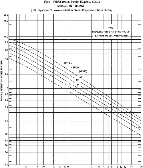
Rainfall intensity shall be determined from the rainfall frequency curves shown in Figure 1 or from data shown in Table 3. The time of concentration (tc) to be used shall be the sum of the inlet time and drainage area to the point under consideration. The flow time in the storm sewers may be estimated by the distance in feet divided by velocity of flow in feet per second. The velocity shall be determined by the Manning Formula.
Inlet time is the combined time required for the runoff to reach the inlet of the storm sewer. It includes overland flow time and flow time through established surface drainage channels such as swales, and ditches, and sheet flow across such Areas as lawns, fields, and other graded surfaces. It may be computed by using Figure 2.
B. The runoff rate for Areas in excess of 200 acres shall be determined by methods described in SECTION 3, X., F.
Table 1 - Urban Runoff Coefficients (1)
| Type of Surface Pavement | Runoff Coefficient "C" |
| Asphalt and Concrete | 0.70 to 0.95 |
| Brick | 0.70 to 0.85 |
| Roofs | 0.75 to 0.95 |
| Lawns (Sandy soil) | |
| Flat (0-2% Slope) | 0.05 to 0.10 |
| Average (2-7% Slope) | 0.10 to 0.15 |
| Steep (7% & Greater) | 0.15 to 0.20 |
| Lawns (Heavy soil) | |
| Flat (0-2% Slope) | 0.13 to 0.17 |
| Average (2-7% Slope) | 0.18 to 0.22 |
| Steep (7% & Greater) | 0.25 to 0.35 |
| Water Impoundment | 1.0 |
(1) HERPICO; Stormwater Drainage Manual; July, 1994.
The coefficients of this tabulation are applicable to storms of 5 to 10 year frequencies. Coefficients for less frequent higher intensity storms shall be modified as follows (Note that "C" should never be greater than 1.):
| Return Period (yrs) | Multiply "C" by |
| 25 | 1.1 |
| 50 | 1.2 |
| 100 | 1.25 |
(2) Marshall County, Indiana, Storm Drainage and Sediment Control Ordinance, October 1993.Â
TABLE 1A
Rural Runoff Coefficients (1)
Type of Surface Runoff Coefficient "C"
Vegetation and Topography Open Sandy Silt Clay and Silt Loam Tight Clay
Flat (0-5% Slope)
Rolling (5-10% Slope)
Steep (greater than 10%)
Woodland
Flat
Rolling
Steep 0.10
0.25
0.30 0.30
0.35
0.50 0.40
0.50
0.60
---------------------------------------------------------------------------
Pasture
Flat
Rolling
Steep 0.10
0.16
0.22 0.30
0.36
0.42 0.40
0.55
0.60
---------------------------------------------------------------------------
Cultivated
Flat
Rolling
Steep 0.30
0.40
0.52 0.50
0.60
0.72 0.60
0.70
0.82
(1) HERPICO; Stormwater Drainage Manual; July, 1994.
The coefficients of this tabulation are applicable to storms of 5 to 10 year frequencies. Coefficients for less frequent higher intensity storms shall be modified as follows (Note that "C" should never be greater than 1):(2)
| Return Period (Yrs.) | Multiply "C" by |
| 25 | 1.1 |
| 50 | 1.2 |
| 100 | 1.25 |
(2) Marshall County, Indiana, Storm Drainage and Sediment Control Ordinance, October 1993.
Table 2
Runoff Coefficients "C"
By Land Use and Typical Inlet Times(1)
Land Use Runoff Coefficients (1) Inlet Time (2)
Flat Rolling Steep (minutes)
Commercial (CBD) 0.75 0.83 0.91 5
Commercial (Neighborhood) 0.54 0.60 0.66 Â
Industrial 0.63 0.70 0.77 5-10
Garden Apartments 0.54 0.60 0.66
Churches 0.54 0.60 0.66
Schools 0.31 0.35 0.39 10-15
Semi Detached Residential 0.45 0.50 0.55
Detached Residential 0.40 0.45 0.50
Quarter Acre Lots 0.36 0.40 0.44
Half Acre Lots 0.31 0.35 0.39
Parkland 0.18 0.20 0.22 To Be Computed
- Flat terrain 0-2% slopes.
- Rolling terrain 2-7% slopes.
- Steep terrain greater than 7% slopes.
- Interpolation, extrapolation and adjustment for local conditions shall all be based on engineering experience and judgment.
- The coefficients of this tabulation are applicable to storms of 5 to 10 year frequencies. Coefficients for less frequent higher intensity storms shall be modified as follows ("C" should never be greater than 1):
| Return Period (Yrs.) | Multiply "C" by |
| 25 | 1.1 |
| 50 | 1.2 |
| 100 | 1.25 |
(1) Marshall County, Indiana, Storm Drainage and Sediment Control Ordinance, October 1993.
 |
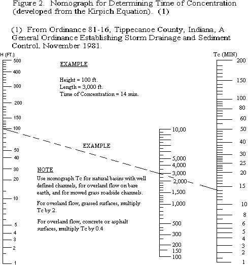 |
TABLE 3
RAINFALL INTENSITIES FOR VARIOUS RETURN
PERIODS AND STORM DURATIONS FOR SOUTH BEND, INDIANA (1)
Return Period (yrs)
Time (hrs) 2 5 10 20 50 100
Extrapolated from HYDRAIN 0.083 5.063 5.898 6.443 7.009 7.716 8.233
0.167 3.961 4.713 5.212 5.738 6.405 6.900
0.25 3.195 3.889 4.357 4.855 5.495 5.973
0.5 2.184 2.726 3.098 3.501 4.026 4.423
-----------------------------------------------------------------
Actual Data
from Analysis 1 - 1.119 1.460 1.686 1.903 2.183 2.393
2 - 0.707 0.916 1.054 1.187 1.359 1.488
3 - 0.531 0.692 0.798 0.900 1.032 1.130
4 - 0.420 0.542 0.624 0.701 0.802 0.878
5 - 0.351 0.452 0.519 0.583 0.666 0.728
6 - 0.303 0.387 0.443 0.495 0.565 0.616
7 - 0.272 0.348 0.399 0.448 0.512 0.559
8 - 0.244 0.315 0.362 0.407 0.465 0.508
9 - 0.220 0.283 0.326 0.366 0.418 0.458
10 - 0.201 0.260 0.299 0.336 0.385 0.421
11 - 0.185 0.240 0.277 0.312 0.357 0.391
12 - 0.172 0.223 0.257 0.290 0.332 0.364
13 - 0.162 0.210 0.241 0.271 0.311 0.340
14 - 0.154 0.200 0.230 0.259 0.296 0.324
15 - 0.146 0.190 0.219 0.247 0.283 0.310
16 - 0.138 0.180 0.207 0.234 0.268 0.293
17 - 0.132 0.171 0.198 0.223 0.256 0.280
18 - 0.126 0.163 0.188 0.212 0.243 0.266
19 - 0.121 0.157 0.180 0.203 0.233 0.255
20 - 0.115 0.149 0.172 0.194 0.223 0.244
21 - 0.110 0.143 0.165 0.186 0.214 0.234
22 - 0.106 0.138 0.159 0.179 0.205 0.225
23 - 0.102 0.133 0.173 0.198 0.217 0.217
24 - 0.099 0.128 0.148 0.167 0.191 0.210
25 - 0.096 0.124 0.143 0.162 0.185 0.203
26 - 0.093 0.120 0.138 0.155 0.177 0.193
27 - 0.090 0.116 0.133 0.149 0.170 0.186
28 - 0.088 0.112 0.129 0.145 0.165 0.180
29 - 0.086 0.110 .0126 0.142 0.162 0.176
30 - 0.084 0.107 0.123 0.138 0.158 0.172
31 - 0.082 0.106 0.121 0.136 0.156 0.171
32 - 0.080 0.103 0.118 0.132 0.151 0.165
33 - 0.078 0.100 0.114 0.128 0.147 0.160
34 - 0.076 0.097 0.112 0.125 0.143 0.156
35 - 0.074 0.095 0.109 0.122 0.139 0.152
36 - 0.072 0.092 0.105 0.118 0.134 0.146
Table 9. Intensity-duration-frequency tables for South Bend with data extrapolated from HYDRAIN for durations smaller than 1 hour.
(1) Marshall County, Indiana, Storm Drainage and Sediment Control Ordinance, October 1993.
V. Amount of Runoff to be Accommodated by Various Parts of Drainage Facility
Various parts of drainage facility must accommodate runoff water as follows:
A. The minor drainage system such as inlets, catch basins, street gutters, swales, sewers, and small channels which collect storm water must accommodate peak runoff from a 10-year return period storm. Rainfall duration shall be equal to the time of concentration or one hour if the time of concentration is less than one hour. A first quartile storm distribution shall be used for computer modeling. These minimum requirements must be satisfied:
The allowable spread of water on Collector Streets is limited to maintaining two clear 10 foot moving lanes of traffic. One lane is to be maintained on Local Roads, while Places can have a water spread equal to one-half of their width.
Open channels carrying peak flows greater than 30 cubic feet per second shall be capable of accommodating peak runoff for a 50-year return period storm within the drainage easement.
Culverts shall be capable of accommodating peak runoff from a 50-year return period storm when crossing under a road which is part of the Indiana Department of Transportation rural functional classification system and are classified as principal or minor arterial, major or minor collector roads.
B. Major drainage systems are defined in SECTION 1, XI., subsection DD and shall be designed in accordance with Indiana Department of Natural Resources Standards as described in SECTION 1, X.
VI. Storm Sewer Design Standards
All storm sewers, whether private or public, and whether constructed on private or public property shall conform to the design standards and other requirements contained herein.
A. Manning's Equation
The hydraulic capacity of storm sewers shall be determined using Manning's Equation:
![]()
V = mean velocity of flow in feet per second
R = the hydraulic radius in feet
S = the slope of the energy grade line in feet per foot
n = roughness coefficient
The hydraulic radius, R, is defined as the cross sectional area of flow divided by the wetted flow surface or wetted perimeter. Typical "n" values and maximum permissible velocities for storm sewer materials are listed in Table 4. Roughness coefficient (n) values for other sewer materials can be found in standard hydraulics tests and references.
B. Minimum Size
The minimum size of all storm sewers shall be 12 inches. Rate of release for detention storage shall be controlled by an orifice plate or other devices, subject to approval of the Sanitary Board of Trustees, where the 12 inch pipe will not limit rate of release as required.
C. Grade
Sewer grade shall be such that, in general, a minimum of two feet of cover is maintained over the top of the pipe. Pipe cover less than the minimum may be used only upon approval of the Sanitary Board of Trustees. Uniform slopes shall be maintained between inlets, manholes and inlets to manholes. Final grade shall be set with full consideration of the capacity required, sedimentation problems and other design parameters. Minimum and maximum allowable slopes shall be those capable of producing velocities of 2.5 and 15 feet per second, respectively, when the sewer is flowing full.
D. Alignment
Storm sewers shall be straight between manholes insofar as possible. Deflection of pipe sections shall not be permitted.
|
Table 4 Typical Values of Manning's "n" |
| Material | Manning's n | Desirable Maximum Velocities |
| Closed Conduits | ||
| Concrete | 0.013 | 15 f.p.s. |
| Vitrified Clay | 0.013 | 15 f.p.s. |
| Brick | 0.015 | 15 f.p.s. |
| Cast Iron | 0.013 | 15 f.p.s. |
| Circular Corrugate Metal Pipe (Annular Corrugations, 2-2/3 x 1/2 in.) |
||
| 12" | 0.011 | |
| 18" | 0.013 | |
| 24" | 0.015 | |
| 36" | 0.018 | |
| 48" | 0.020 | |
| 60" or larger | 0.021 |
| Corrugated Plyethylene Smooth Interior Pipe | 0.012 | 15 f.p.s. |
| Concrete Culverts | 0.013 |
| Open Channels | ||
| Concrete, Trowel Finish | 0.013 | |
| Concrete, Broom or Float Finish | 0.015 | |
| Gunite | 0.018 | |
| Riprap Placed | 0.030 | |
| Riprap Dumped | 0.035 | |
| Gabion | 0.028 | |
| New Earth (Uniform, Sodded, Clay) | 0.025 | |
| Existing Earth (Fairly Uniform, w/Some Weeds) | 0.030 | |
| Dense Growth of Weeds | 0.040 |
| Dense Weeds and Brush | 0.040 | |
| Swale with Grass | 0.035 |
E. Manholes
Manholes shall be installed to provide access to continuous underground storm sewers for the purpose of inspection and maintenance.
Manholes shall be provided at the following locations:
- Where two or more storm sewers converge.
- At the point of beginning or at the end of a curve, and at the point of reverse curvature (PC, PT, PRC).
- Where pipe size changes.
- Where an abrupt change in alignment occurs.
- Where a change in grade occurs.
- At suitable intervals in straight sections of sewer.
The maximum distance between storm sewer manholes shall be as follows:
| Size of pipe (inches) | Maximum Distance (feet) |
| 12 thru 42 | 400 |
| 48 and larger | 500 |
F. Inlets
Inlets or drainage structures shall be utilized to collect surface water through grated openings and convey it to storm sewers, channels, or culverts. Inlet design and spacing shall be in accordance with Section 7-400 of the Indiana Department of Transportation's Road Design Manual - Volume 1 or other approved design procedure. The inlet grate opening provided must be adequate to pass the design 10 year flow with 50% of the sag inlet Areas clogged. An overload channel from sag inlets to the overflow channel or basin shall be provided at sag inlets, so that the maximum depth of water that might be ponded in the street sag shall not exceed 7 inches.
VII. Workmanship and Materials of Storm Sewers
A. Workmanship
The specifications for the construction of storm sewers shall not be less stringent than those set forth in the latest edition of the Indiana Department of Transportation's "Standard Specifications"; additionally, ductile iron pipe shall be laid in accordance with American Water Works Association (AWWA) C-600, and plastic pipe shall in laid in accordance with the American Society of Testing Materials (ASTM) D-2321.
B. Materials
Storm sewer manholes and inlets shall be constructed of masonry, cast-in-place concrete or precast reinforced concrete. Material and construction shall conform to Indiana Department of Transportation's "Standard Specifications", Section 720.
Pipe and fittings used in storm sewer construction shall be ductile iron pipe (AWWA C-151), concrete pipe (ASTM C-76), acrylonitrile-butadiene-styrene pipe (ASTM D-2751), or polyvinyl chloride pipe (ASTM D-2729). Other pipe and fittings not specified herein may be used only when specifically authorized by the Sanitary Board of Trustees. Pipe joints shall be flexible and watertight and shall conform to the requirements of Section 715.02 - Materials, of the latest edition of the Indiana Department of Transportation's "Standard Specifications".
C. Special Hydraulic Structures
Special hydraulic structures required to control the flow of water in storm runoff drainage systems include junction chambers, drop manholes, inverted siphons, stilling basins, and other special structures. The use of these structures shall be limited to those locations justified by prudent planning and by careful and thorough hydraulic engineering analysis.
VIII. Open Channel Design Standards
All open channels, whether private or public, and whether constructed on private or public land, shall conform to the design standards and other design requirements contained herein.
A. Manning's Equation
The waterway for channels shall be determined using Manning's Equation.
Mannings Equation 2 link
Where: A = Waterway area of channel in square feet
Q = Discharge in cubic feet per second (cfs)
V, R, S & n are explained in Paragraph VI.,A.
B. Channel Cross Section and Grade
The required channel cross section and grade are determined by the design capacity, the material in which the channel is to be constructed, and the requirements for maintenance. A minimum depth may be required to provide adequate outlets for subsurface drains, tributary ditches, or streams. The channel grade shall be such that the velocity in the channel is high enough to prevent siltation but low enough to prevent erosion. Velocities less than 1.5 feet per second should be avoided because siltation will take place and ultimately reduce the channel cross section. The maximum permissible velocities in vegetal-lined channels are shown in Table 5. Developments through which the channel is to be constructed must be considered in design of the channel section.
C. Side Slopes
Earthen channel side slopes shall be no steeper than 3 to 1. Flatter slopes may be required to prevent erosion and for ease of maintenance. Where channels will be lined, side slopes shall be no steeper than 1.5 to 1 with adequate provisions made for weep holes.
Side slopes steeper than 1.5 to 1 may be used for lined channels provided that the side lining and structural retaining wall are designed and constructed with provisions for live and dead load surcharge.
D. Channel Stability
1. Characteristics of a stable channel are:
- It neither aggrades nor degrades beyond tolerable limits.
- The channel banks do not erode to the extent that the channel cross section is changed appreciably.
- Excessive sediment bars do not develop.
- Excessive erosion does not occur around culverts, bridges or elsewhere.
- Gullies do not form or enlarge due to the entry of uncontrolled surface flow to the channel.
2. Channel stability shall be determined for an aged condition and the velocity shall be based on the design flow or the bank full flow, whichever is greater, using "n" values for various channel linings as shown in Table 4. In no case is it necessary to check channel stability for discharges greater than that from a 100 year return period storm.
3. Channel stability must be checked for conditions immediately after construction. For this stability analysis, the velocity shall be calculated for the expected flow from a ten-year return period storm on the watershed, or the bank full flow, whichever is smaller. The "n" value for newly constructed channels in fine-grained soils and sands may be determined in accordance with the National Engineering Handbook 5, Supplement B, Soil Conservation Service and shall not exceed 0.025. The allowable velocity in the newly constructed channel may be increased by a maximum of 20 percent to reflect the effects of vegetation to be established under the following conditions:
- The soil and site in which the channel is to be constructed are suitable for rapid establishment and support of erosion controlling vegetation.
- Species of erosion controlling vegetation adapted to the area, and proven methods of establishment are shown.
- The channel design includes detailed plans for establishment of vegetation on the channel side slopes.
|
Table 5 Maximum Permissible Velocities in Vegetal-Lined Channels (1) |
| Permissible Velocity | Slope Range (2) (Percent) | Erosion Resistant Soils (ft. per sec) | Easily Eroded Soils (ft. per sec.) |
| Cover | 0-5 | 8 | 6 |
| Bermuda | 5-10 | 7 | 5 |
| Grass | Over 10 | 6 | 4 |
| Bahia | |||
| Buffalo grass | |||
| Kentucky bluegrass | 0-5 | 7 | 5 |
| Smooth brome | 5-10 | 6 | 4 |
| Blue grama | Over 10 | 5 | 3 |
| Grass mixtures (2) | 0-5 | 5 | 4 |
| Reed canarygrass | 5-10 | 4 | 3 |
| Lespediza sericea | |||
| Weeping lovegrass | |||
| Yellow bluestem (3) | 0-5 | 3.4 | 2.5 |
| Redtop | |||
| Alfalfa | |||
| Red fescue |
| Common lespedeza (4) | 0-5 | 3.5 | 2.5 |
| Sudangrass (5) |
(1) Use velocities exceeding 5 feet per second only where good covers and proper maintenance can be obtained.
(2) Do not use on slopes steeper than 10 percent except for vegetated side slopes in combination with a stone, concrete, or highly resistant vegetative center section.
(3) Do not use on slopes steeper than 5 percent except for vegetated side slopes in combination with stone, concrete, or highly resistant vegetative center section.
(4) Annuals--use on mild slopes or as temporary protection until permanent covers are established.
(5) Use on slopes steeper than 5 percent is not recommended.
(1) From Soil Conservation Service, SCS-TP-61, Handbook of Channel Design for Soil & Water Conservation.
E. Drainage of Waterways
Vegetated waterways that are subject to low flows of long duration or where wet conditions prevail shall be drained with a tile system or by other means such as paved gutters. Tile lines may be outletted through a drop structure at the end of the waterway or through a standard tile outlet.
F. Establishment of New Regulated Drain
The Marshall County Drainage Board may mandate that storm drains and detention basins in residential subdivisions become regulated drains to insure the proper maintenance of the system. If the Board mandates the establishment of a new Regulated Drain, each developer must provide the necessary information and meet the requirements of the 1965 Indiana Drainage Code, as amended, for the establishment of a new Regulated Drain. The Marshall County Drainage Board shall determine the necessary easements for adequate maintenance of any new Regulated Drain.
G. Appurtenant Structures
The design of channels will provide all structures required for the proper functioning of the channel and the laterals thereto and travelways for operation and maintenance. Recessed inlets and structures needed for entry of surface and subsurface flow into channels without significant erosion or degradation shall be included in the design of channel improvements. The design is also to provide the necessary flood gates, water level control devices, and any other appurtenance affecting the functioning of the channels and the attainment of the purpose for which they are built.
The effect of channel improvements on existing culverts, bridges, buried cables, pipelines, and inlet structures for surface and subsurface drainage on the channel being improved and laterals thereto shall be evaluated to determine the need for modification or replacement. Culverts and bridges which are modified or added as part of channel improvement projects shall meet reasonable standards for the type of structure, and shall have a minimum capacity equal to the design discharge or governmental agency design requirements, whichever is greater.
H. Disposition of Spoils
Spoil material resulting from clearing, grubbing and channel excavation shall be disposed in such a manner which will:
- Minimize overbank wash.
- Provide for the free flow of water between the channel and floodplain unless the valley routing and water surface profile are based on continuous dikes being installed.
- Not hinder the development of travelways for maintenance.
- Leave the right-of-way in the best condition feasible, consistent with the project purposes, for productive use by the owner.
- Improve the aesthetic appearance of the site to the extent feasible.
- Be approved by the Indiana Department of Natural Resources or US Army Corps of Engineers (whichever is applicable) if deposited in the floodway.
IX. Construction and Materials of Open Channels
A. Construction
Specifications shall be in keeping with the current standards of engineering practice and shall describe the requirements for proper installation of the project to achieve its intended purpose.
B. Materials
Materials acceptable for use as channel lining are:
- Grass
- Revetment Riprap
- Concrete
- Hand-laid Riprap
- Precast Cement Concrete Riprap
- Grouted Riprap
- Gabions
Other lining materials shall receive specific approval of the Sanitary Board of Trustees. Materials shall comply with the latest edition of the Indiana Department of Transportation's "Standard Specifications".
X. Storm Water Detention
The following shall govern the design of any improvement with respect to the detention of stormwater runoff.
A. Acceptable Detention Methods
The increased stormwater runoff resulting from a proposed development should be detained on-site by the provisions of appropriate wet or dry bottom reservoirs, by storage on flat roofs, parking lots, streets, lawns, or other acceptable techniques. Measures which retard the rate of overland flow and the velocity in runoff channels shall also be used to control the runoff rate partially. Detention basins shall be sized to store excess flows from storms with a one hundred (100) year return period. Control devices shall limit the discharge to a rate no greater than that prescribed by this ordinance (see SECTION 3, X., E. and F.).
B. Design Storm
Design of storm water detention facilities shall be based on a return period of once in 100 years. The storage volume and outflow rate shall be sufficient to handle storm water runoff from a 24 hour duration storm, as defined in SECTION 3, X., E. and F. Rainfall intensity-duration-frequency relationships shall be those given in Table 3.
C. Allowable Release Rate
The allowable release rate of storm water originating from a proposed development shall not exceed the amount specified in SECTION 1, II. - Storm Water Control Policy, and as described in SECTION 3, X., E. and F.
In the event the storm sewer system is inadequate to accommodate the release rate provided above, then the allowable release rate shall be reduced to that rate permitted by the capacity of the receiving storm sewer system, and additional detention as determined by the Sanitary Board of Engineers shall be required to store that portion of the runoff exceeding the capacity of the receiving sewers or waterways.
If more than one detention basin is involved in the development of the area upstream of the limiting restriction, the allowable release rate from any one detention basin shall be in direct proportion to the ratio of its drainage area to the drainage area of the entire watershed upstream of the restriction.
D. Drainage System Overflow Design
Drainage systems shall have adequate capacity to convey the storm water runoff from all upstream tributary Areas through the development under consideration for a storm of 100 year design return period calculated on the basis of the upstream land in its present state of development. An allowance, equivalent to the reduction in flow rate provided, shall be made for upstream detention when such upstream detention and release rate have previously been approved by the Sanitary Board of Trustees and evidence of its construction can be shown.
E. Determination of Storage Volume - Rational Method
For Areas of two hundred (200) acres or less, the Rational Method may be used to determine the required volume of storm water storage. The following eleven step procedure may be used to determine the required volume of storage. Other design methods may also be used, subject to approval of the Sanitary Board of Trustees, and as described in SECTION 3, X., F.
Steps Procedure:
- Determine total drainage area in acres "A".
- Determine composite runoff coefficient "Cu" based on existing land use (undeveloped).
- Determine time of concentration "tc" in minutes based on existing conditions.
- Determine rainfall intensity "Iu" in inches per hour, based on time of concentration and using FIGURE 1 or from data given in Table 3 for the ten (10) year return period.
- Compute runoff based on existing land use (undeveloped), and ten (10) year return period:
Qu = CuIuA - Determine composite runoff coefficient "Cd" based on developed conditions and a one hundred (100) year return period.
- Determine the one hundred (100) year return period rainfall intensity "Id" for various storm durations "td" up through the time of concentration for the developed area using Table 3.
- Determine developed inflow rates "Qd" for various storm durations "td", measured in hours.
Qd = CdIdA - Compute a storage rate "Std" for various storm durations "td" up through the time of concentration of the developed area.
Std = Qd - Qu - Compute required storage volume "SR" in acre-feet for each storm duration "td". This assumes a triangular hydrograph of duration (2*td) hours with the peak flow of Std at td hours.
SR = Std (td/12) - Select the largest storage volume computed in step 10 for detention basin design.
F. Determination of Storage Volume - Other Methods
Methods other than the rational method for determining runoff and routing of storm water may be used to determine the storage volume required to control stormwater runoff. The procedures or methods used must receive the prior approval of the Sanitary Board of Trustees. The ILLUDAS, TR-20 and TR-55 models are approved by the Sanitary Board of Trustees for appropriate use in analysis of the runoff and routing of storm water. The use of these models or other approved procedures can be defined in a seven step procedure to determine the required storage volume of the detention basin(s).
Step Procedure:
- Calibrate the hydrologic/hydraulic model that is to be used for prediction of runoff and routing of storm water.
- For each storm duration listed in Table 3, perform steps three through six.
- Determine the ten (10) year, undeveloped peak flow. Denote this flow by Qu10.
- Determine the one hundred (100) year runoff hydrograph (Hd100) for developed conditions.
- Determine the hydrograph that must be stored (Hs100) by subtracting a flow up to Qu10 from the hydrograph (Hd100) found in step 4.
- Determine the volume of water (Vs) to be stored by calculating the area under the hydrograph Hs100.
- The detention basin must be designed to store the largest volume (Vs) found for any storm duration analyzed in step 6.
G. General Detention Basin Design Requirements:
Basins shall be constructed to detain temporarily the storm water runoff which exceeds the maximum peak flow rate authorized by this Ordinance. The volume of storage provided in these basins, together with such storage as may be authorized in other on-site facilities shall be sufficient to control excess runoff from the one hundred (100) year storm.
The following design principles shall be observed:
- The maximum volume of water stored and subsequently released at the design release rate shall not result in a storage duration in excess of 48 hours unless additional storms occur within the period.
- The maximum planned depth of storm water stored (without a permanent pool) shall not exceed four feet.
- All storm water detention facilities shall be separated by not less than 75 feet from any building or structure to be occupied.
- All excavated excess spoil may be spread so as to provide for aesthetic and recreational features such as sliding hills, sports fields, etc. Slopes no steeper than 6 horizontal to 1 vertical for safety, erosion control, stability, and ease of maintenance shall be permitted.
- Safety screens having a maximum opening of 4 inches shall be provided for any pipe or opening to prevent children or large animals from crawling into the structures.
- Danger signs shall be mounted at appropriate locations to warn of deep water, possible flooding conditions during storm periods and other dangers that exist. Fencing shall be provided if deemed necessary by the Sanitary Board of Trustees.
- Outlet control structures shall be designed to operate as simply as possible and shall require little or no maintenance and/or attention for proper operation. They shall limit discharges into existing or planned downstream channels or conduits so as not to exceed the predetermined maximum authorized peak flow rate.
- Emergency overflow facilities such as a weir or spillway shall be provided for the release of exceptional storm runoffs or in emergency conditions should the normal discharge devices become totally or partially inoperative. The overflow facility shall be of such design that its operation is automatic and does not require manual attention.
- Grass or other suitable vegetative cover shall be provided throughout the entire basin area. Grass should be cut regularly at approximately monthly intervals during the growing season or as required.
- Debris and trash removal and other necessary maintenance shall be performed on a regular basis to assure continued operation in conformance to design.
- A report shall be submitted with the preliminary or final plan as stated in SECTION 3, I., F.
H. Dry Bottom Basin Design Requirements
Detention basins which will not contain a permanent pool of water shall comply with the following requirements:
- Provisions shall be incorporated to facilitate complete interior drainage of dry bottom basins, to include the provisions of natural grades to outlet structures, longitudinal and transverse grades to perimeter drainage facilities, paved gutters, or the installation of subsurface drains.
- The detention basin shall, whenever possible, be designed to serve a secondary or multipurpose function. Recreational facilities, aesthetic qualities (open spaces) or other types of use shall be considered in planning the detention facility.
I. Wet Bottom Basin Design Requirements
Where part of a detention basin will contain a permanent pool of water, all the items required for detention storage shall apply except that the system of drains with a positive gravity outlet required to maintain a dry bottom basin will not be required. A controlled positive outlet will be required to maintain the design water level in the wet bottom basin and provide required detention storage above the design water level.
However, the following conditions shall apply:
- Basins designed with permanent pools or containing permanent ponds shall have a water area of at least one-half acre. If fish are to be maintained in the pond, a minimum depth of approximately 10 feet shall be maintained over at least 25 percent of the pond area. The remaining pond area shall have no extensive shallow areas, except as required by subsection (3) below.
- In excavated ponds, the underwater side slopes in the pond shall be stable. In the case of valley storage, natural slopes may be considered to be stable.
- A safety ledge four to six feet in width is required and must be installed in all ponds approximately 30 to 36 inches below the permanent water level. In addition, a similar maintenance ledge 12 to 18 inches above the permanent water line shall be provided. The slope between the two ledges shall be stable and of a material such as stone or riprap which will prevent erosion due to wave action.
- A safety ramp exit from the pond is required in all cases and shall have a minimum width of 20 feet and exit slope of 6 horizontal to 1 vertical. The ramp shall be of a material that will prevent its deterioration due to vehicle use and/or wave action.
- Periodic maintenance is required in ponds to control weed and larval growth. The pond shall also be designed to provide for the easy removal of sediment which will accumulate during periods of pond operation. A means of maintaining the designed water level of the pond during prolonged periods of dry weather is also required.
- For emergency use, basin cleaning, or shoreline maintenance, facilities shall be provided or plans prepared for auxiliary equipment to permit emptying and drainage.
- Facilities to enhance and maintain pond water quality shall be provided, if required to meet applicable water quality standards. Design calculations to substantiate the effectiveness of these aeration facilities shall be submitted with final engineering plans. Agreements for the perpetual operation and maintenance of aeration facilities shall be prepared to the satisfaction of the Sanitary Board of Trustees.
J. Roof Top Storage
Detention storage requirements may be met in total or in part by detention on flat roofs. Details of such designs are to be included in the building permit application and shall include the depth and volume of storage, details of outlet devices and downdrains, and elevations of emergency overflow provisions.
K. Parking Lot Storage
Paved parking lots may be designed to provide temporary detention storage of storm waters on all or a portion of their surfaces. Outlets will be designed so as to empty the stored waters slowly. Depths of storage must be limited to a maximum depth of 7 inches so as to prevent damage to parked vehicles and so that access to parked vehicles is not impaired. Ponding should, in general, be confined to those positions of the parking lots farthest from the area served.
L. Facility Financial Responsibility
The construction cost of storm water control systems and facilities as required by this ordinance shall be accepted as part of the cost of land development. If general public use of the facility can be demonstrated, negotiations for public participation in the cost of such development may be considered.
M. Facility Maintenance Responsibility
Maintenance of detention/retention facilities during construction and thereafter, shall be the responsibility of the land developer/owner. Assignment of responsibility for maintaining facilities serving more than one lot or holding shall be documented by appropriate covenants to property deeds, unless responsibility is formally accepted by a public body, and shall be determined before the final drainage plans are approved.
Storm water detention and retention basins may be donated to the City or other unit of government designated by the City, for ownership and permanent maintenance providing:
- The City or other governmental unit is willing to accept responsibility.
- The facility has been designed and constructed according to all applicable provisions of this ordinance.
- All improvements have been constructed, approved, and accepted by the governmental agency for the land area served by the drainage basin.
- Detention ponds containing a permanent pool of water have all slopes between the riprap and high water line sodded and the remaining land area hydroseeded; are equipped with electrically driven aeration devices, if required to maintain proper aerobic conditions and sustain aquatic life; have a four-foot wide crushed limestone walkway at the high water line entirely around the body of water; provide suitable public access acceptable to the responsible governmental agency; and have the high water line not closer than 75 feet to any property line.
- Dry detention ponds shall have all slopes, bottom of the basin and Areas above the high water line hydroseeded; and shall have the high water line not closer than 50 feet to any development boundary.
N. Inspections
All public and privately owned detention storage facilities can be inspected by representatives of the City not less often than once every 2 years. If inspected, a certified inspection report covering physical conditions, available storage capacity and operational condition of key facility elements will be provided to the owner.
O. Corrective Measures
If deficiencies are found by the inspector, the owner of the detention/retention facility will be required to take the necessary measures to correct such deficiencies. If the owner fails to do so, the City will undertake the work and collect from the owner using lien rights, if necessary.
P. Joint Development of Control Systems
Storm water control systems may be planned and constructed jointly by two or more developers as long as compliance with this Ordinance is maintained.
Q. Installation of Control Systems
Runoff and erosion control systems shall be installed as soon as possible during the course of site development. Detention/ retention basins shall be designed with an additional (six) percent of available capacity to allow for sediment accumulation resulting from development and to permit the pond to function for reasonable periods between cleanings. Basins should be designed to collect sediment and debris in specific locations so that removal costs are kept to a minimum.
R. Detention Facilities in Floodplains
If detention storage is provided within a floodplain, only the net increase in storage volume above that which naturally existed on the floodplain shall be credited to the development. No credit will be granted for volumes below the elevation of the regulatory flood at the location unless compensatory storage is also provided.
S. Off-Site Drainage Provisions
When the allowable runoff is released in an area that is susceptible to flooding, the developer may be required to construct appropriate storm drains through such area to avert increased flood hazard caused by the concentration of allowable runoff at one point instead of the natural overland distribution. The requirement of off-site drains shall be at the discretion of the Sanitary Board of Trustees.
XI. Other Requirements
A. Sump Pumps
Sump pumps installed to receive and discharge groundwaters or other storm waters shall be connected to the storm sewer where possible or discharged into a designated storm drainage channel. Sump pumps installed to receive and discharge floor drain flow or other sanitary sewage shall be connected to the sanitary sewers. A sump pump shall be used for one function only, either the discharge of storm waters or the discharge of sanitary sewage.
B. Down Spouts
All down spouts or roof drains shall discharge onto the ground or be connected to the storm sewer. No down spouts or roof drains shall be connected to the sanitary sewers.
C. Footing Drains
Footing drains shall be connected to storm sewers where possible or designated storm drainage channels. No footing drains or drainage tile shall be connected to the sanitary sewer.
D. Basement Floor Drains
Basement floor drains shall be connected to the sanitary sewers.
The Plymouth Park Department offers the following shelters for reservations seven days a week beginning April 1st through October 15th.
Each site has a "Family Style" grill.
Click here to review our rental policy.
Hoosier Old Wheels
This shelter is located on the north side of Centennial Park. A very popular area because it is next to a large playground. The shelter has a small kitchen, restrooms & seats approximately 100 people.
Cost:
- Resident - $50.00/day plus sales tax
- Non-Resident - $80.00/day plus sales tax
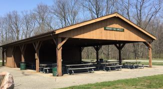
Freymen Shelter
This shelter is located on the north side of Centennial Park next to the tennis complex and soccer fields. This is the largest shelter in the park. It has a nice kitchen facility, restrooms, ample parking space and seating for 150 people.
Cost:
- Resident - $50.00/day plus sales tax
- Non-Resident - $80.00/day plus sales tax

VFW Shelter
This shelter is located in River Park Square next to the Senter Stage amphitheater. This is our newest shelter throughout the park system. It features a permanent set of cornhole boards (made of concrete) and a naturalistic playground directly north of the shelter.
Cost:
- Resident - $50.00/day plus sales tax
- Non-Resident - $80.00/day plus sales tax
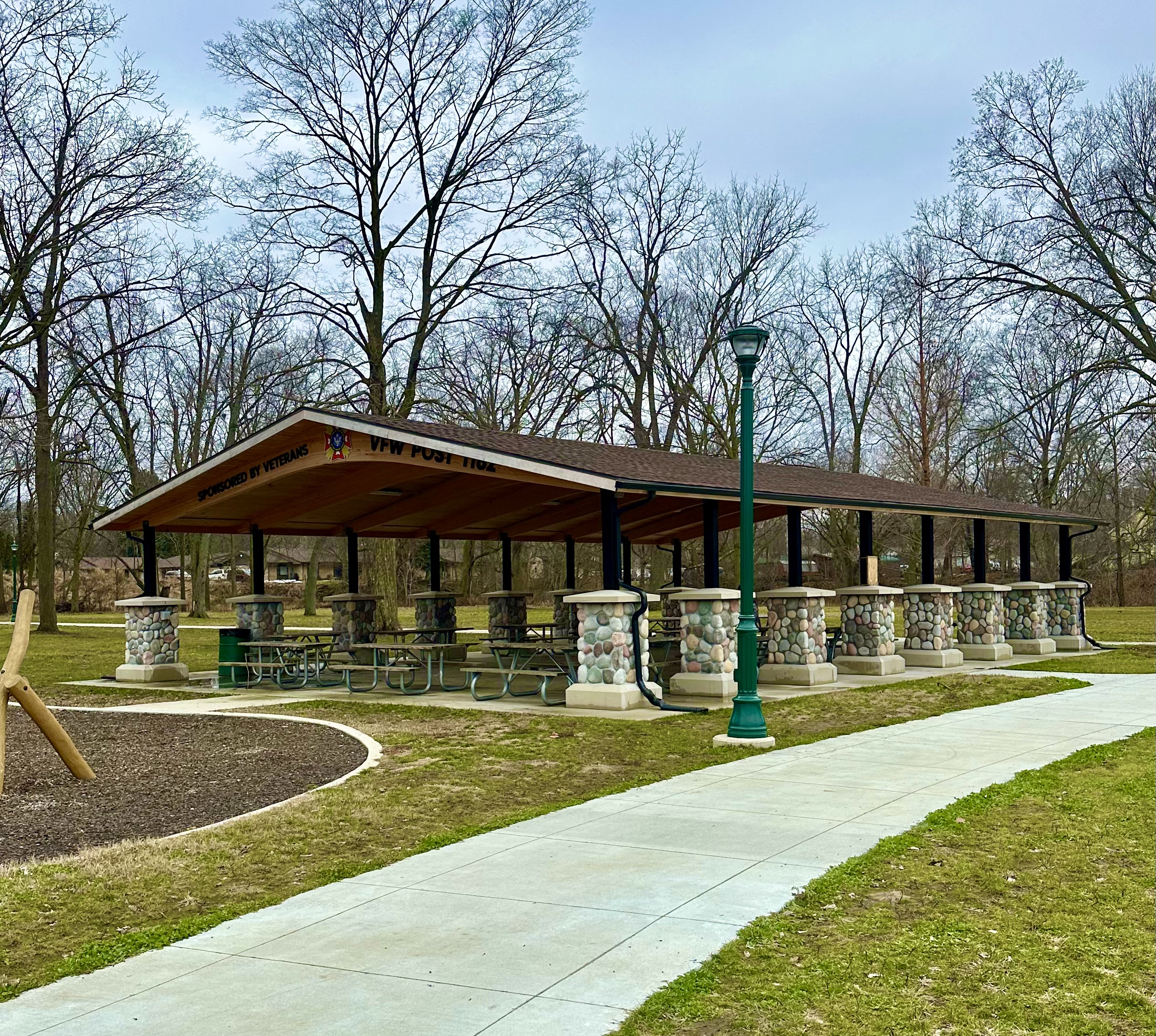
Lions Club Shelter
This shelter is tucked neatly into an area next to the shuffleboard courts and has restrooms. Users will find they have easy access to the walking trails and tennis courts. Seating is for 60 people.
Cost:
- Resident - $30.00 plus sales tax
- Non-Resident - $50.00 plus sales tax

Rotary Shelter
This shelter is also on the north side of Centennial Park next to the shuffleboard courts. Users will find electrical outlets and water nearby. Seating is for 60 people.
Cost:
- Resident - $30.00 plus sales tax
- Non-Resident - $50.00 plus sales tax

Roadrunner Shelter
This shelter is the park's newest shelter. It is located in Centennial Park next to Symphony Restaurant. It has electrical outlets and water nearby. Users will be a short walk from the playground, pool, volleyball courts and softball diamond. Seating is for 125 people.
Cost:
- Resident - $30.00 plus sales tax
- Non-Resident - $50.00 plus sales tax

Masons Shelter/Neidlinger Shelter
These shelters are located across from the pool and close to the playground. It also has electrical outlets and water nearby. Seating is for 75 people.
Cost:
- Resident - $30.00 plus sales tax
- Non-Resident - $50.00 plus sales tax
 |
 |
Horsebarn
This unique shelter is located next to the covered bridge in Centennial Park. Users will find themselves in the heart of the park with access to all facilities within walking distance. The building is enclosed with the exception of sliding doors on each end. Electrical outlets and water are available. Seating inside for 100 - 125 people.
Cost:
- Resident - $50.00 plus sales tax
- Non-Resident - $80.00 plus sales tax
 |
 |
 |
Packard's Woods Red/Blue Pavilions
These shelters are located in Packard's Woods off of Harrison Street by the new Freedom Park play structure. They have electrical outlets and water nearby. Seating is for 60 people for each pavilion. The Red shelter is closest to the playground and the Blue shelter is closest to the diamond.
Cost:
- Resident - $30 plus sales tax
- Non-Resident - $50 plus sales tax
 |
 |
Price's Pond Front/Back Pavilions & Gazebo
Price's Memorial Park: This is the newest acquisition of the Plymouth Park Department. Bob Price donated the facility to the Park Department in October of 2015. Price’s Memorial Park is located on the North side of Plymouth off of Plymouth Goshen Trail. On the 13 acre property there is a pond that consists of approximately 3 acres. There are two shelters and one gazebo. Each of the shelters can seat up to 75 people. There is a playground on the property as well as a house. 205 Plymouth Goshen Trail, Plymouth, IN 46563
Cost:
- Resident - $50.00 plus sales tax
- Non-Resident - $80.00 plus sales tax
Rent the whole park for $750.00 plus tax and has a $200.00 refundable deposit.
 |
 |
 |

Click the link to locate parks and shelters on a map.
MCM#1 - Public Education and Outreach
- Public Survey
- Web Page Development
- Printed Materials
- Educational Display
- Storm Drain Labeling
MCM#2 - Public Participation and Involvement
- Public Presentation
- Children Education
- Household Hazardous Waste Programs
MCM#3 - Illicit Discharge Detection and Elimination
- Storm Sewer Mapping Program
- Legal Enforcement
- Field Assessments
MCM#4 - Construction Site Runoff Control
- Appoint Construction Storm Water Manager
- Develop Ordinance
- Develop Plan Review Protocols
- Develop Site Inspection Procedures
- Develop Public Reporting Procedures
MCM#5 - Post-Construction Site Runoff Control
- Hold Meetings with Boards
- Develop New Standards
- Enforce New Standards
MCM#6 - Pollution Prevention and Good Housekeeping
- Street Sweeping & Cleaning
- Sidewalks & Parking Lots
- Medians, Parks & Landscape
- Storm Drain System Cleaning
- Structural Best Management Practices (BMP) Program
- Develop Rule 6 List
- Rule 6 Reviews
This Ordinance - Policy establishes standards for permitting Small Cell Facilities and associated supporting structures within the public right-of-way of the City of Plymouth, Indiana, in order to promote the orderly growth of needed wireless communications infrastructure, while ensuring the public health, safety, and welfare of the community.
Ordinance NO. 2019-2146, An Ordinance Regarding the Permitting of Wireless Facilities and Wireless Support Structures Within the Public Right-of-Way.
The City recommends that, prior to filing an application for a permit under this Policy, that an Applicant engage the City staff to assist the Applicant’s Small Cell Facility development team with troubleshooting preliminary siting and design concerns. During such pre-application period of engagement, to the extent practicable, the City will aid the Applicant in discovering existing conditions and access to the proposed site area.
Small Cell Facility Applications must be filled out in order to install a Small Cell Facility on City owned property/Right of Way. The applications provide general information regarding the Small Cell Facility & the development team which serves as a summary for the required engineering designs & details. The application is reviewed and approved by the Technical Review Committee.
A Work in the Right-of-Way Application needs to be submitted to the City of Plymouth and approved by the Board of Public Works and Safety for work to be performed in the Right-of-Way. A License Agreement shall be executed and a cash financial guarantee shall be posted with the City of Plymouth Board of Public Works & Safety prior to the granting of the Permit to work in the Right-of-Way. The financial guarantee is based on the damage risk to the City Utilities.
NOTE: It should be noted that all Contractors working in the City of Plymouth must be registered with the City of Plymouth Building Commissioner.
Upon completion of the project a set of as-built drawings and a Completion Affidavit shall be submitted to the City of Plymouth. Once reviewed and inspected the City shall release the financial guarantee upon faithful performance of the conditions set forth in the License Agreement.
More information coming soon.
More information coming soon.
More information coming soon.
Useful Links
- Indiana Storm Water Field Guide
- Plymouth 2040 Comprehensive Plan
- 2040 comprehensive plan survey flyer
- Laborer Maintenance (Park) Job Description
- Covid-19 Resources - Spanish Version
- Republic Services - What Can Be Recycled
- Disc Golf Map
- City of Plymouth Employee Handbook (December 2024)
- United States Department of Labor
Upcoming Events
- Board of Public Works and Safety Meeting00/28/256:00 pm - 11:59 pm
- Common Council Meeting30/28/256:30 pm - 11:59 pm
- Plan Commission Meeting - CANCELLED00/06/257:00 pm - 11:59 pm
Contact Us
Contact Us
Contact Us

Building Commissioner
- Phone: (574) 936-2824
- Fax:
(574) 936-5256 - Staff Directory
Contact Us

Planning Director
- Assistant: (574) 936-6717 x 1113
- Staff Directory
Contact Us
Planning Director
Contact Us

Superintendent
- Business: (574) 936-3410
- Fax:
(574) 936-3520 - Staff Directory
- Hours: M - F 7:00 a.m. - 3:30 p.m.
Contact Us

City Engineer, Plan Commissioner
- Business: (574) 936-3614
- Fax:
(574) 936-3017 - Staff Directory
- Hours: M - F 7:00 a.m. - 3:00 p.m.
Contact Us
- Phone: (574) 936-3614
- Fax:
(574) 936-3017 - Staff Directory
- Hours: M - F 7:00 a.m. - 3:00 p.m.
Contact Us

Fire Chief
- Phone: (574) 936-2156
- Fax:
(574) 936-5256 - Staff Directory
Contact Us

Mayor
- Business: (574) 936-6717
- Staff Directory
- Hours: M - F 8:00 a.m. - 4:45 p.m.
Contact Us

Manager
- Business: (574) 935-5152
- Staff Directory
- Hours: M - Th. 8:00 a.m. - 6:00 p.m.
Fri. 8:00 a.m. - 5:00 p.m.
Contact Us
Manager
- Phone: (574) 935-5152
- Staff Directory
- Hours: M - Th. 8:00 a.m. - 6:00 p.m.
Fri. 8:00 a.m. - 5:00 p.m.
Contact Us

Park Superintendent
- Business: (574) 936-2876
- Fax:
(574) 936-1951 - Staff Directory
- Hours: M - F 8:00 a.m. - 4:00 p.m.
Contact Us
- Phone: (574) 936-2876
- Staff Directory
- Hours: M - F 8:00 a.m. - 4:00 p.m.
Contact Us

Police Chief
- Business: (574) 936-2126
- Staff Directory
- Hours: 24hrs/Day
Contact Us
Police Chief
- Phone: (574) 936-2126
- Staff Directory
- Hours: 24 Hours
Contact Us

Street Superintendent
- Business: (574) 936-2017
- Fax:
(574) 936-3551 - Staff Directory
- Hours: M - F 8:00 a.m. - 3:30 p.m.
Contact Us

Clerk-Treasurer
- Business: (574) 936-2124
- Fax:
(574) 936-4371 - Staff Directory
- Hours: M - F 8:30 a.m. - 4:30 p.m.
Contact Us

Utility Superintendent
- Business: (574) 936-3017
- Staff Directory
- Hours: M - F 7:00 a.m. - 4:00 p.m.
Contact Us
Contact Us
Utility Superintendent
Plymouth, IN 46563
- Phone: (574) 936-2543
- Staff Directory
- Hours: M - F 7:30 a.m. - 4:30 p.m.
Contact Us

City Attorney
- Business: (574) 936-6717
- Staff Directory
Contact Us
- Phone: (574) 936-6717
- Staff Directory
- Hours: M - F 8:30 a.m. - 4:30 p.m.
Contact Us
- Phone: (574) 936-6717
- Staff Directory
- Hours: M - F 8:30 a.m. - 4:30 p.m.
Contact Us
- Phone: (574) 936-6717
- Staff Directory
- Hours: M - F 8:30 a.m. - 4:30 p.m.
Contact Us
- Phone: (574) 936-3614
- Fax:
(574) 936-3017 - Staff Directory
Contact Us
- Phone: (574) 936-3614
- Fax:
(574) 936-3017 - Staff Directory
Contact Us
- Phone: (574) 936-3614
- Fax:
(574) 936-3017 - Staff Directory
Contact Us
Contact Us
- Phone: (574) 936-3410
- Fax:
(574) 936-3520 - Staff Directory
- Hours: M - F 7:00 a.m. - 3:30 p.m.
Contact Us
- Phone: (574) 936-3410
- Fax:
(574) 936-3520 - Staff Directory
- Hours: M - F 7:00 a.m. - 3:30 p.m.
Contact Us
- Phone: (574) 936-3410
- Fax:
(574) 936-3520 - Staff Directory
- Hours: M - F 7:00 a.m. - 3:30 p.m.
Contact Us
- Phone: (574) 936-2124
- Fax:
(574) 936-4371 - Staff Directory
- Hours: M - F 8:30 a.m. - 4:30 p.m.
Contact Us
- Phone: (574) 936-2124
- Fax:
(574) 936-4371 - Staff Directory
- Hours: M - F 8:30 a.m. - 4:30 p.m.
Contact Us
- Phone: (574) 936-2124
- Fax:
(574) 936-4371 - Staff Directory
- Hours: M - F 8:30 a.m. - 4:30 p.m.
Contact Us
- Phone: (574) 936-2156
- Fax:
(574) 936-5256 - Staff Directory
Contact Us
- Phone: (574) 936-2156
- Fax:
(574) 936-5256 - Staff Directory
Contact Us
- Phone: (574) 936-2156
- Fax:
(574) 936-5256 - Staff Directory
Contact Us
- Phone: (574) 936-2126
- Staff Directory
- Hours: 24 Hours/Day
Contact Us
- Phone: (574) 936-3614
- Fax:
(574) 936-3017 - Staff Directory
Contact Us
- Phone: (574) 936-3614
- Fax:
(574) 936-3017 - Staff Directory
Contact Us
- Phone: (574) 936-3614
- Fax:
(574) 936-3017 - Staff Directory
Contact Us
- Phone: (574) 936-3614
- Fax:
(574) 936-3017 - Staff Directory
Contact Us
- Phone: (574) 936-2368
- Staff Directory
- Hours: M - F 7:00 a.m. - 4:00 p.m.
Contact Us
Fire Chief
- Phone: (574) 936-2156
- Fax:
(574) 936-5256 - Staff Directory
Contact Us
Contact Us
Human Resources Manager
- Business: (574) 914-0502
- Staff Directory
- Hours: Monday - Friday 8:30am - 4:00pm